ALU Main Component Overview
↠Back to the Legends Ultimate Guide
Last Update:8/20/2021
Author: dudemo
The guide below will provide an overview of the main components within the AtGames Legends Ultimate (ALU). The following information was compiled by a kind reddit member, dudemo and wanted to make it available to you. I’m hosting the information below to assist others that may want to tinker/mod their AtGames Legends Ultimate or get a better understanding of the inner-workings of the ALU.
*NOTE: Anything you find on this section of the guide will completely void any warranty remaining on your machine. Attempt with great care, always disconnect all power to the ALU before attempting any modifications to your machine. You accept full liability for any damage caused by any modifications you make.
Table of Contents
Overview of Components
This is a basic overview of the components inside the control panel of the Legends Ultimate and Gamer Pro. Most the hardware discussed below is also being used within a number of other Legends platform products, such as: the Legends Mini, Ultimate Mini, Legends Pinball control panel and perhaps others.
Requirements
- #3 jewelers philips screwdriver
- #2 standard philips screwdriver with 6″ shaft
- 3-in-1 oil or white lithium grease
- Sheldon Sims trackball shim kit (Optional but recommended)
Disconnect all power and connections going to the panel and remove from the ALU. Remove the 8 screws on the bottom of the control panel. Make sure the USB/Power/Data ports are pointing TOWARDS YOU! When you remove the bottom, be very careful because the plate around the USB / Power / Data connectors makes it very tight and difficult to remove. DO NOT JUST RIP UP ON IT! The pinball buttons are wired to the encoder and the wires do NOT give you much room. So be patient and work carefully.
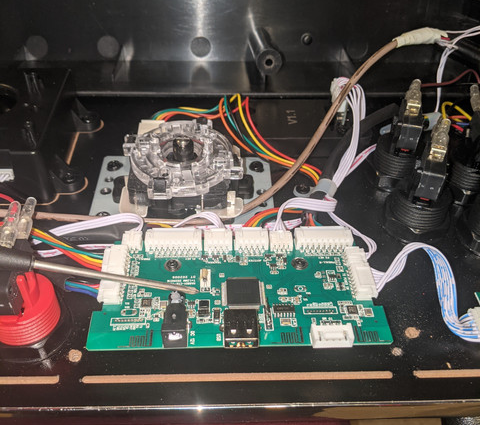
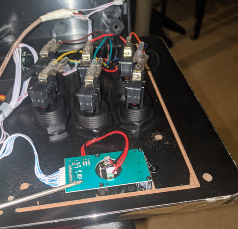
Once you get the case free, rotate the case away from you. I had it on a computer chair, which helped hold the case out of my way. The first thing you’ll see is the encoder:

This little guy is the “brain” or Main Board of the control panel. Everything plugs into this. If you have issues with buttons, joysticks, spinners, or the trackball, this should be the first thing you check. So while you have it open and are looking at it, go ahead and firmly but gently ensure that all the wires are seated properly.
Joysticks
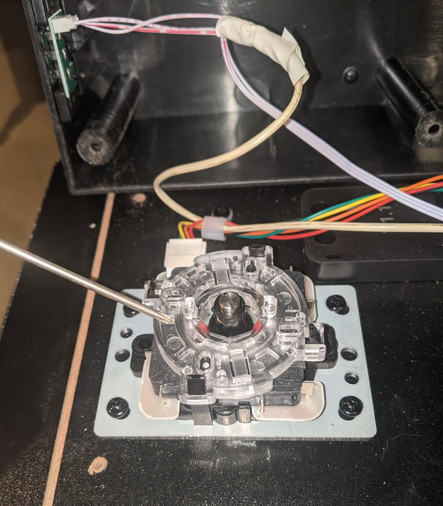
In the above image, the joysticks are essentially basic Sanwa clones. They even use the standard Sanwa 5 wire harness. Easily swappable with any other Sanwa clone. *Note: the flathead screw slot on the center shaft. This is how you remove the ball top if you want to replace it with the more well known American “bat top” style top. If you look at the wires above the joystick on the bottom case, that is the pinball button pogo connector as well as the wires mentioned earlier.
Buttons
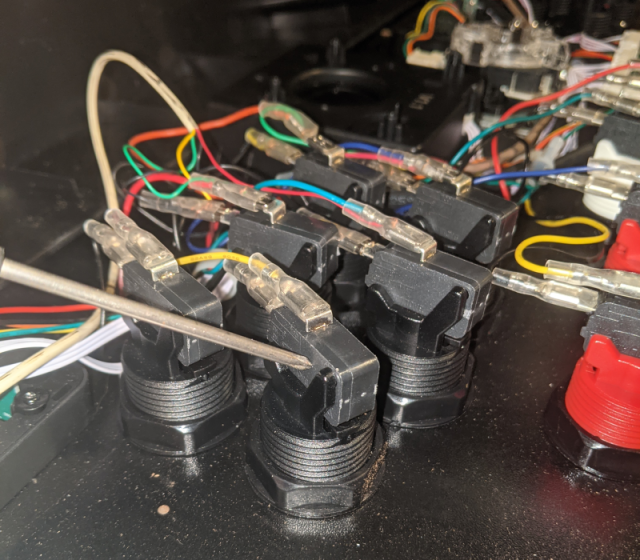
The buttons are basically Happ buttons with 30g switches. All of them are basically standard arcade buttons and can be replaced very easily and cheaply. You may want to consider getting an arcade button wrench, they are inexpensive.
Spinners
Player 2 spinner is actually the primary spinner. Player 1 spinner is wired into Player 2 spinner. Fun fact: In the firmware, each spinner is detected as different axis of a mouse. Player 2 controls up/down, player 1 controls left/right!
Power Button
Not much to see here. Just a simple power switch with LED.
Trackball
Last, but certainly not least, is the trackball. This guy is pretty important because it is the only part that isn’t user replaceable (WTT Note: Glen @ Glen’s Retro Show posted pictures recently of an ALU-compatible trackball that will be coming in 2021). At present, no suitable replacement for the trackball is available. As such, we really do need to know how to maintain the ball so it stays optimum for Golden Tee, Centipede, and Irritating Maze. Below is an image of the bottom side of the trackball assembly:
There are three screws we need to pay attention to. One of them is in a little track and it is more important than the other ones as it adjusts how freely the ball spins. Take these three screws out, but make sure you have your hand under the ball because it will drop out. Set the ball and the ring aside for now.
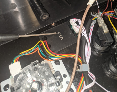
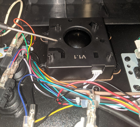
Once you have the ball out, there are 4 screws that hold in the casing. Unplug the casing before removing these screws. Below, I point to one of them.
In the image below, I am pointing to the wires that run really close to the trackball casing. When re-assembling the casing in the control panel, the wires kept wanting to get under the casing. Just pointing that out because they can be pretty pesky.
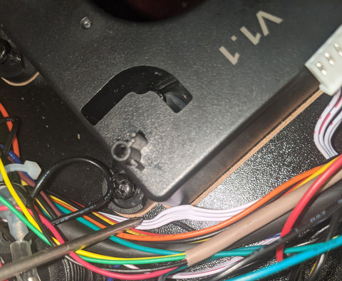
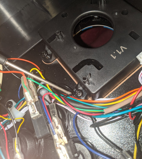
Once you have the casing out, we can start removing the bowl so we can get to the bearings underneath. There are 4 screws that hold the bowl on. Here I point to one of them. Remove them and lift off the bowl. Underneath is a small circuit board and a few roller shafts with bearings. Its the bearings we care about. Here, I point to both a bearing and a shaft:
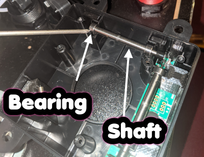
There are two long shafts that control direction and one guide shaft that is much smaller. Just like an old ball mouse, these can get pretty grimed up and need cleaning. Isopropyl alcohol is your friend in that regard. But overtime, the bearings can also lose some of their spin and need some grease. Grab that 3-in-1 oil or white lithium grease. Remember, LESS IS MORE! If you get the stuff all over the roller shafts, the ball will no longer grip with the roller shaft and the ball will be useless. So, you want to be precise with your oil and use only what is necessary. The roller shafts lift out easily, so this should be very easy to do.
While we are on that note of lifting out the shafts, the two directional shafts have “optical” wheels on one end. Here is a photo of them:
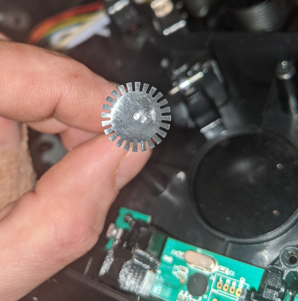
Pay attention to see if any teeth are broken. These are replacable, but very hard to get off the shaft. Be careful with them. Put it all back together when you get done greasing the bearings. You really should do this. Now. Go grease them. They need it.
When you put the ball back together, do not overtighten the screws that hold on the ring. It tightens down pretty hard on the ball and doesn’t allow it to move freely. You’ll have to tear the whole thing back apart just to loosen them. Trust me on this.
When you put the whole thing back together, be very careful and do not overtighten the screws that hold on the bottom case. AtGames used some really short screws because they used some really thin MDF for the control panel to shave down weight. As such, these screws strip VERY EASILY! Just a heads up.
I think that about covers it. Originally I was going to cover replacing the encoder with an IPAC2 encoder, but if you are using a Raspberry Pi with RetroPie, it uses libSDL2 for encoder mappings, which is also what the AtGames encoder uses. Since libSDL2 is actually used in the Legends firmware with permission, the libSDL2 developers actually worked with AtGames to get the encoder included in the libraries. As such, the AtGames encoder works out of the box with a Raspberry Pi running RetroPie. So this part was not necessary.
Happy modding everyone!
–Dudemo
Change Log
- 2021-08-16 – 2021-08-20– Start and continuation of this guide.